Description
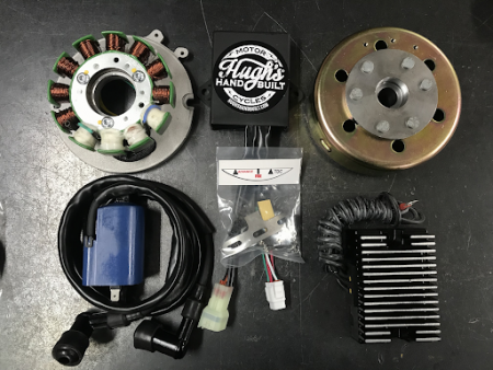
With a few thousand of these kits sold, it only makes sense that we are now seeing a few folks needing replacement parts. The Majority of the issues we have seen have been due to improper install, poor wiring connection, grounds not proper, etc.. Blame it on the previous owner, I would.
So, if you are in need, we got you! I’ll be creating a video on testing all of these components as well, but until then, the specs below should help you decide what components you might need to repair your Hugh’s HandBuilt CDI System.
*Note, ALL Specs unless mentioned otherwise are with the component removed from the bike, not running, etc.
IGNITION COMPONENT TESTS:
Stator Specs:
- Red to Green Wires: 12-25 Ohms Resistance
- If not in spec, inspect wires for damage, and make sure the solder connection at the windings is intact.
- NO connectivity from ANY wire to the body of the stator/ground.
Ignition Pickup Specs:
- White/Red Stripe Wire to White/Green Stripe Wire: 92-138 Ohms Resistance
- If not in spec, inspect wires for damage from pinching/rubbing/grounding out.
- Resistance between any wire to Metal Tab/Ground on Pickup: OL (no connectivity)
- ANY indication of impact from the timing tab can damage this component.
- Clearance spec is VERY important. Must have MIN .015″ Between Pickup and Entirety of Timing Tab after install.
Ignition Coil Specs:
- Primary (Between 2 Spade Terminals on Coil): 1.5-3.0 Ohms Resistance
- Secondary (Between Spark Plug Wires): 13-15K Ohms
- If out of spec, remove spark plug wires from coil (they unscrew from the coil) and test at the coil itself. This will rule out Spark Plug Wires/Caps as a Failure
- ANY Primary Terminals to ANY Secondary Plug Wire: OL
- Any Resistance here will be the reason the coil fires on only 1 Cylinder
CDI Box Test:
- TEST Ignition Coil, Pickup Coil, and Stator Windings FIRST. Then REMOVE the 87a Terminal from the supplied Relay (if using Relay) and see if the engine runs. If it does, suspect the relay. If those are in spec, Relay Terminal 87a removed and still no spark, its ok to suspect the CDI Box. Its very rare for one of these boxes to go bad unless directly shorted out somewhere or physically damaged. There is no other bench test for the CDI Box. I am happy to test it on my system here in house if you mail it in of course.
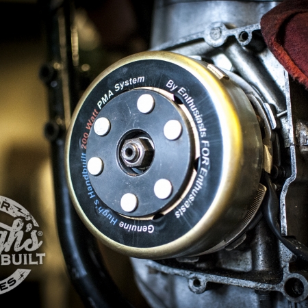
Flywheel:
- Inspect for Physical Damage
- Any damage from wrong puller being used, hammer marks, internal rubbing against stator, metal trash on the magnets, etc.
- Inspect M4 Tapped Threads. If these are damaged, replace the flywheel.
Timing Tab:
- Should be without any evidence of contact with the Ignition Pickup – Clearance should be MIN .015″ between tab and pickup at ANY location.
- Any evidence of damage to adjustment slots or evidence of contact with Ignition Pickup warrants replacement.
- If Timing Tab is Damaged, assume Ignition Pickup is also damaged.
Various Wiring Connectors/Hardware:
- If damage to connectors has occurred, replace the connectors.
- Use correct Crimpers (Such as the RMStator Pliers in our store)
- We also offer the same connectors in a complete kit for wiring your entire bike.
- This gives plenty of spare connectors in case of a botched crimp, etc.
Relay/Wire Harness:
- Relay Basically provides a 12V- “Kill” to the CDI box using the 12V+ On/Off or Key Switch on your bike.
- Removing Terminal 87a from the Relay Harness will bypass the Relay and allow engine to run. If 87a being removed allows engine to run, inspect Your Switched 12V+ wiring source.
- Inspect wiring for chafing, pinching, damage, etc. Any damage to Harness should be corrected for proper function of CDI System.
CHARGING COMPONENT TESTS:
Stator Tests (do NOT test with the bike running):
- Yellow to Yellow Wires: .3-1.0 Ohms Resistance
- If not in spec, inspect wires for damage, and make sure the solder connection at the windings is intact.
- NO connectivity from ANY wire to the body of the stator/ground.
MOSFET Regulator Test:
Voltage OUTPUT Test:
- Make Sure Body of Regulator is Grounded to Chassis
- Make sure Connections to battery or capacitor are in good shape
- With Engine Running, output at the Battery/Capacitor: 12.0-14.7V
- Check at Idle, and with Throttle.
- ~1000 RPM: 12-13.5V
- ~5000 RPM: 14.6-14.8V
- Check at Idle, and with Throttle.
Diode Testing:
- With Engine OFF, and Regulator Removed From Chassis for Diode Testing:
- Set Meter to Diode Test Function (Google the setting if you need to)
- Red Wire from Voltage Meter to 12V+ Output Wire On Regulator
- Black Wire from Voltage Meter to Either of the Stator Input Wires (test both): OL (no connectivity)
- Black Wire from Voltage Meter to 12V+ Output Wire On Regulator
- Red Wire from Voltage Meter to Either of the Stator Input Wires (test both): .1-.6
- Red Wire from Voltage Meter to BODY (ground) of the Voltage Regulator
- Black Wire from Voltage Meter to Either of the Stator Input Wires (test both): .1-.6
- Black Wire from Voltage Meter to BODY (Ground) of the Voltage Regulator
- Red Wired from Voltage Meter to Either of the Stator Input Wires (test both): OL (no connectivity)
- Red Wire from Voltage Meter to 12V+ Output Wire On Regulator
- Any Failure of these tests indicate a Bad Regulator and it should be replaced.
- Set Meter to Diode Test Function (Google the setting if you need to)
Various Wiring Connectors/Hardware:
- If damage to connectors has occurred, replace the connectors.
- Ensure proper crimps on wire connectors/harness connections
- Use correct Crimpers (Such as the RMStator Pliers in our store)
- We also offer the same connectors in a complete kit for wiring your entire bike.
- This gives plenty of spare connectors in case of a botched crimp, etc.



Reviews
There are no reviews yet.